Automatic Sliding Door Controller
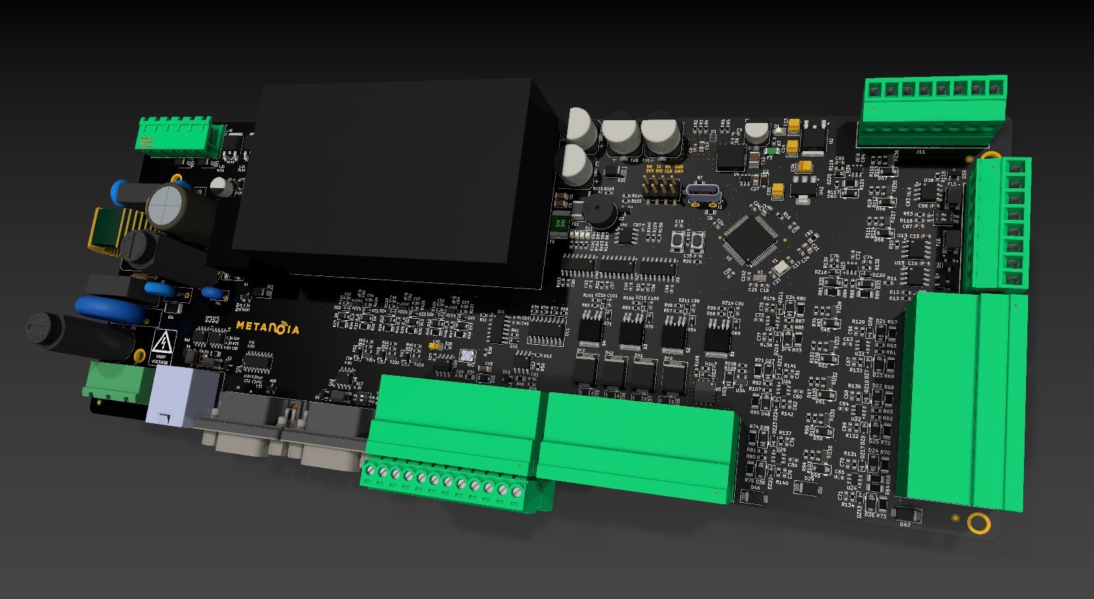
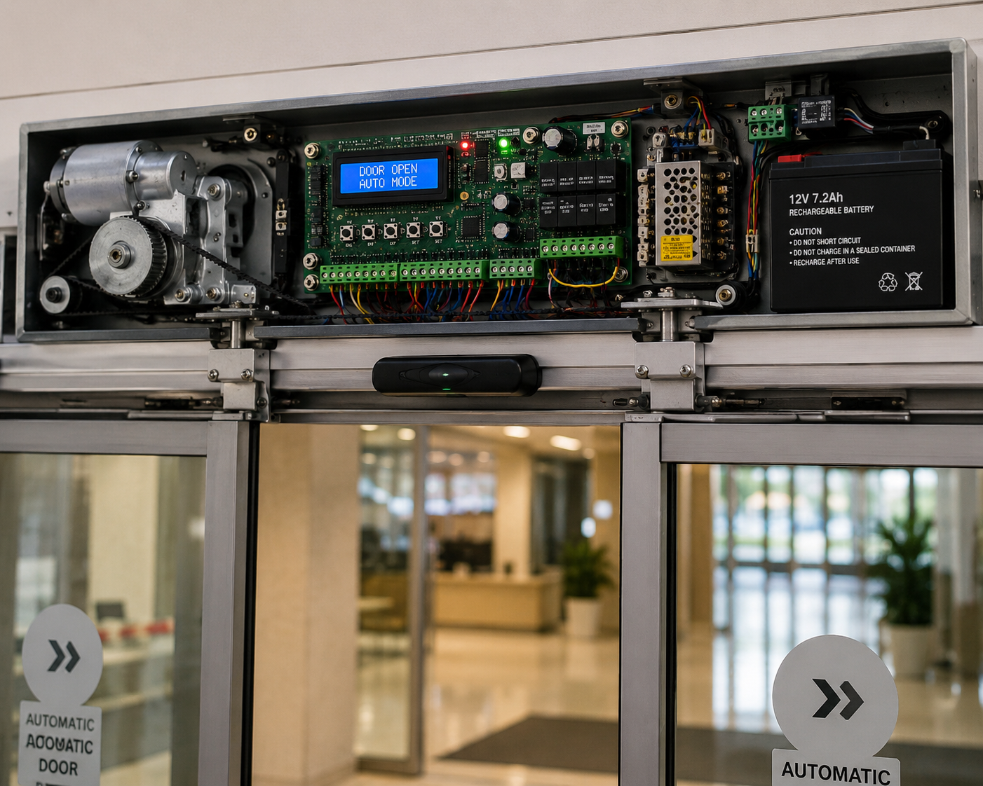
A custom electronic controller for automatic sliding doors, designed to manage motor movement, obstacle detection, opening and closing sequences, battery backup, and safe daily operation.
Project Overview
The Automatic Sliding Door Controller was developed as a complete control system for automatic entrance doors used in commercial, industrial, and public buildings.
The controller manages the full opening and closing cycle, monitors the motor position, detects obstacles, responds to external activation signals, and switches to battery power during electrical interruptions.
The system was designed to provide smooth movement, reliable operation, and improved safety during continuous daily use.
Client Requirements
The client needed a custom controller capable of:
- Operating a 24 V DC sliding-door motor.
- Monitoring door position using an encoder.
- Detecting people or obstacles during movement.
- Opening the door from external switches or sensors.
- Controlling opening and closing speed.
- Providing smooth acceleration and deceleration.
- Stopping or reversing the door when an obstacle is detected.
- Supporting battery backup during power failure.
- Receiving a dry-contact activation signal.
- Supporting manual and automatic operating modes.
- Providing status and fault indication.
- Working reliably during frequent daily operation.
Our Solution
Metanoia designed a complete automatic-door control solution including:
- Controller architecture.
- Power and motor-control circuits.
- Microcontroller-based control logic.
- Encoder feedback interface.
- Obstacle and safety sensor inputs.
- Limit and position detection.
- Battery charging and switchover circuit.
- Dry-contact activation input.
- User settings and operating modes.
- Fault detection and protection.
- PCB design and manufacturing.
- Firmware development.
- Assembly, soldering, and testing.
The controller was designed as a compact system that can be integrated into different sliding-door mechanisms.
Main Features
Motor Direction Control
The controller operates the motor in both directions to open and close the sliding door.
Encoder Feedback
The encoder provides movement and position feedback, allowing the controller to:
- Monitor door travel.
- Detect movement interruptions.
- Control the stopping position.
- Improve opening and closing accuracy.
Smooth Start and Stop
The motor speed is gradually increased and reduced to provide:
- Smoother movement.
- Lower mechanical stress.
- Reduced noise.
- Better user experience.
Obstacle Detection
When an obstacle is detected during closing, the controller can:
- Stop the motor.
- Reverse the door direction.
- Reopen the door.
- Prevent unsafe closing.
External Activation
The controller can receive opening commands from:
- Motion sensors.
- Push buttons.
- Access-control systems.
- Dry-contact outputs.
- Remote-control modules.
Battery Backup
The system can continue operating during a power interruption using a backup battery.
The charging and switchover circuit manages:
- Battery charging.
- Automatic power transfer.
- Battery-voltage monitoring.
- Low-battery protection.
Operating Modes
The controller can support modes such as:
- Automatic.
- Always open.
- Locked.
- Manual.
- One-way entry.
- Maintenance mode.
Status and Fault Monitoring
The system can indicate:
- Door open.
- Door closed.
- Motor movement.
- Obstacle detection.
- Battery operation.
- Sensor faults.
- Motor overload.
- Encoder errors.
Engineering Challenges
Accurate Door Position
The controller needed to know the door position without relying only on fixed timing.
Encoder feedback was used to monitor movement and improve position accuracy.
Safe Obstacle Response
The door must react immediately when a person or object is detected.
The firmware was designed to stop and reverse the motor based on safety-sensor input.
Smooth Motor Movement
Starting and stopping the motor suddenly can cause noise and mechanical stress.
A controlled speed profile was implemented to provide gradual acceleration and deceleration.
Battery Power Management
The controller needed to switch between the main supply and battery power without interrupting operation.
A charging and automatic switchover system was included.
Continuous Daily Operation
Automatic doors may operate hundreds of times per day.
The hardware and firmware were designed for repeated operation, fault handling, and recovery.
Development Process
1. System Analysis
The door mechanism, motor specifications, travel distance, activation methods, and safety requirements were studied.
2. Control Architecture
The motor driver, power supply, battery circuit, sensors, encoder, and user interfaces were defined.
3. Schematic Design
The complete electronic schematic was created, including:
- Microcontroller.
- Motor driver.
- Encoder input.
- Safety inputs.
- Power management.
- Battery charging.
- Dry-contact input.
- Protection circuits.
4. PCB Design
The PCB was designed with attention to:
- Motor-current routing.
- Noise reduction.
- Power separation.
- Connector placement.
- Protection.
- Installation accessibility.
5. Manufacturing and Assembly
The PCB was manufactured, assembled, and soldered by Metanoia.
6. Firmware Development
The firmware was developed to manage:
- Door movement.
- Speed control.
- Encoder counting.
- Safety response.
- Operating modes.
- Battery operation.
- Fault detection.
7. Testing and Validation
The controller was tested under repeated opening and closing cycles, sensor activation, obstacle conditions, and power interruption.